Suntouch Promelt Installation Manual
ProMelt Electric Snow melting Mats
By SunTouch® A division of Watts Water Technologies, Inc.
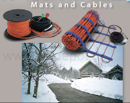
tired of shoveling your snow out to work? Cant drive your car to work? Use SunTouch the snow melting system.
SunTouch ProMelt products are a simple way to eliminate snow and ice from surfaces. This instruction manual is provided as a guide to installing ProMelt Mat and ProMelt Cable, including design considerations, mat and cable installation, control installation, precautions, and surfacing guidelines.
Specifications for ProMelt Mat: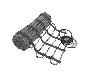
Sizes: Widths 2, 3 feet. Lengths 5 up to 56 feet
Voltages: 120, 208, 240, 277 VAC, 1-phase
Watts: 50 W/sq. ft (170 Btu/h/sq. ft) and 38 W/sq. ft (130 Btu/h/sq. ft)
Maximum heater current: 24 amps
Maximum circuit load: 50 amps
GFCI Class B (ground fault equipment protection) required for each circuit
Listing: ETL Listed for U.S. and Canada under UL 515, IEEE 515.1, and CAN/CSA C22.2 No. 130-03
Listing file number: 3151992
Application: outdoor use only, embedded in concrete, asphalt, sand (see Step 1.1)
Minimum bend radius: 1 inch
Maximum exposure temperature (continuous and storage): 221°F (105°C)
Maximum exposure temperature (short-term for asphalt covering): 285°F (140°C)
Minimum installation temperature: 40°F (4.5°C)
Installation must be performed by qualified personnel, in accordance with local codes, ANSI/NFPA 70 (NEC Article 426) and Section 62 of the CEC Part I.
Specifications for ProMelt Cable:
ProMelt Cable is a complete heating cable consisting of a series resistance heating cable and a single power lead for easy single-point connection. The heating cable length cannot be cut to fit.
Voltages: 120, 208, 240, 277 VAC, 1-phase
Watts: 50 W/sq. ft (170 Btu/h/sq. ft), spaced at 3 inches on-center
38 W/sq. ft (130 Btu/h/sqft), spaced at 4 inches on-center
(Cable is designed to operate at approximately 12.5 W/linear foot of cable at rated voltage.)
Maximum heater current: 24 amps
Maximum circuit load: 50 amps
GFCI Class B (ground fault equipment protection) required for each circuit
Listing: ETL Listed for U.S. and Canada under UL 515, IEEE 515.1, and CAN/CSA C22.2 No. 130-03
Listing file number: 3151992
Application: outdoor use only, embedded in concrete, asphalt, sand (see on this manual)
Minimum bend radius: 1 inch
Maximum exposure temperature (continuous and storage): 221°F (105°C)
Maximum exposure temperature (short-term for asphalt covering): 285°F (140°C)
Minimum installation temperature: 40°F (4.5°C)
WARNING
Installation must be performed by qualified personnel, in accordance with local codes and standards. Read these important warnings and all installation instructions prior to installation. Failure to so do can result in fire, shock, property damage, personal injury and/or death.
NEVER cut or modify the heating cable. The power lead may be cut shorter if necessary, but never removed from the heating cable.
NEVER overlap or cross over the heating cable on itself, or place heating cable closer than 2 inches from another heating cable or power lead cable.
NEVER pull any of the heating cable or factory splices into any conduit.
NEVER attempt to repair a damaged cable. Contact the factory for assistance.
ALWAYS de-energize all circuits before installing or servicing.
ALWAYS completely embed the heating cable and factory splices in concrete, sand, or asphalt.
ALWAYS avoid placing the heating cable any closer than 2 inches from other items such as underground cable or piping to keep from overheating them.
ALWAYS keep ends of the power leads dry before and during installation.
ALWAYS provide ground fault protection (GFCI) for the snow melting system. This may be at the circuit breaker or the control.
ALWAYS pay close attention to voltage and amperage requirements of the circuit breaker, control, and snow melting system.
ALWAYS install in accordance with all local codes and the National Electrical Code (ANSI/ NFPA 70 especially Article 426) and Section 62 of the Canadian Electrical Code (CEC) Part I.
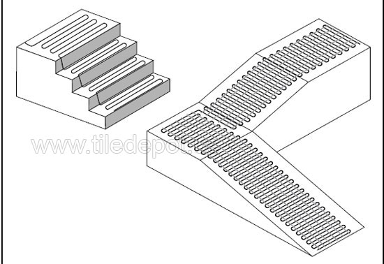
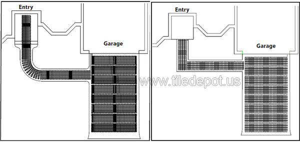
Some Typical ProMelt Installations Ideas
ProMat work well on stairs and Ramps
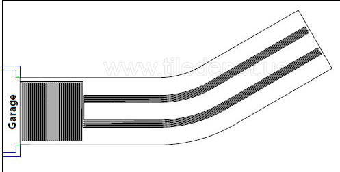
Driveway with full coverage near garage and "tire track" coverage down driveway.
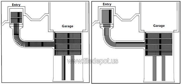
ProMelt Mats and Cables can be used in combination to fit a variety of areas.
Phase 1: Designing the System
STEP 1.1
Determine general areas where you want to install ProMelt Mat/Cable Applications include driveways, walkways, patios, permanent ramps, masonry steps and benches, shipping docks, under garage door seals and more. Anywhere outdoors in residential or commercial locations where snow or ice accumulate may be considered, as long as ProMelt is completely embedded in concrete, sand, thick mortar bed, or asphalt.
ProMelt Mat/Cable cannot be installed indoors, in industrial locations, or areas with hazardous classifications. It cannot be used for gutter or pipe freeze protection or roof snowmelt. Do not install the mat/cable on or under non-masonry stairs or decks such as wooden or composite construction.
If installing ProMelt under brick pavers, we recommend installing cables under the entire area. This is because the non heated area will receive melt water that may re-freeze under the pavers causing the pavers to heave in the non-heated area.
If you have an application you are unsure of, please call the factory for advice.
STEP 1.2
Make a drawing and measure the area where you want snow melting to occur. Eliminate those areas where ProMelt cannot be installed, keeping in mind the following obstructions and allowances:
• Mat/Cable cannot be laid within 6 inches of the edges of slabs. In asphalt, this is increased to 12 inches from the edge where no curb is provided.
• Avoid crossing expansion joints in a slab, unless proper technique and protection steps are followed (see Step 3.14).
• Avoid placing the heating cable any closer than 2 inches from other items such as underground cable or piping to keep from overheating them.
• Allow at least 2 inches between adjacent cables, but not more than 4 inches, between adjacent cables or sections of a mat where the mat mesh is cut and turned to fill the area.
• Mat/Cable must be laid such that the surface will not have other obstructions placed on top, capturing heat or allowing potential damage from mounting brackets, bolts, or similar (pedestals, support columns, walls, light posts, or similar)
Also, consider the following precautions:
WARNING: THE HEATING CABLE CANNOT BE CUT TO LENGTH. Order the correct size mat or cable to fit the area. Modifying the heating cable is not allowed and may lead to overheating, damage, and fire hazard.
• The heating cable and factory splices of ProMelt Mat/Cable must be completely embedded in the concrete, sand, or asphalt. Never try to use up excess heating cable in surrounding soil, walls, or other unprotected applications.
• Never overlap the heating cable on itself or place heating cable closer than 2 inches from other heating cable.
• Only the power lead may exit this area. It will be pulled through conduit to protect it up to a junction box.
NEVER pull any of the heating cable or factory splices into any conduit.
See typical installations on above page.
STEP 1.3
Determine where junction box(es) may be placed to receive the ProMelt Mat/Cable power leads. This is important to ensure the mat(s) and/or cable(s) you select fill the area correctly and with the best connection locations.
It is best to locate junction boxes on a wall indoors and within the distance of the power leads on the mat/cable. ProMelt mat/cable comes standard with 20-foot long power leads, but may be custom ordered up to 50 feet long if necessary.
If a junction box must be located outdoors, it is recommended it be installed above grade and be properly Listed for rain tight use outdoors. If it must be installed at or below grade, use properly Listed watertight items and follow box manufacturer guidelines for protection and connection seals.
STEP 1.4 (ProMelt Mat Only)
Select the ProMelt Mat(s) you need. (for ProMelt Cable sizes see following page)
WATTAGE: Decide what heat output is required. Your design must consider weather conditions and how critical it is
to clear the heated area.
Mat with 50 watts per square foot heat output are sufficient to clear most moderate and heavy snowfall rates.
Mat with 38 watts per square foot heat output are sufficient to clear most light to moderate snowfall rates.
SIZE: ProMelt Mat is manufactured in a variety of sizes as shown in Table 1. If the exact size of mat is not found in the Table, select the next smaller mat size.
AMPS and VOLTS: Pay careful attention to the amps to make sure your controls, circuit breaker panel, and wiring will have the proper capacity. Design everything to handle 125 percent of heating mat load:
- 20 amp circuit for load up to 16 amps
- 30 amp circuit for load up to 24 amps
- 40 amp circuit for load up to 32 amps
- 50 amp circuit for load up to 40 amps
- 70 amp circuit for load up to 50 amps
Table 1 (mat sizes)
|
3' Wide Mats - 50 Watts/Sq. Ft. 208 VAC
|
|
Mat Size |
Coverage Sq. Ft |
Amp Draw |
Ohms |
|
3' x 5' |
15 sq. |
3.6 |
59 - 73 |
|
3' x 10' |
30 sq. |
6.7 |
28 - 34 |
|
3' x 15' |
45 sq. |
11.7 |
15 - 19 |
|
3' x 20' |
60 sq. |
15.0 |
13 - 16 |
|
3' x 25' |
75 sq. |
18.4 |
10 -12 |
|
3' x 30' |
90 sq. |
23.4 |
8 - 10 |
|
3' Wide Mats - 50 Watts/Sq. Ft. 240 VAC
|
|
Mat Size |
Coverage Sq. Ft |
Amp Draw |
Ohms |
|
3' x 5' |
15 sq. |
3.6 |
68 - 83 |
|
3' x 10' |
30 sq. |
7.2 |
32 - 39 |
|
3' x 15' |
45 sq. |
10.8 |
21 -26 |
|
3' x 20' |
60 sq. |
14.4 |
15 - 18 |
|
3' x 25' |
75 sq. |
18.0 |
12 - 14 |
|
3' x 30' |
90 sq. |
21.6 |
10 - 12 |
|
3' x 35' |
105 sq. |
21.9 |
8 - 10 |
|
3' Wide Mats - 50 Watts/Sq. Ft. 277 VAC
|
|
Mat Size |
Coverage Sq. Ft |
Amp Draw |
Ohms |
|
3' x 10' |
30 sq. |
5.0 |
51 - 62 |
|
3' x 15' |
45 sq. |
8.4 |
24 - 30 |
|
3' x 20' |
60 sq. |
11.7 |
21 - 25 |
|
3' x 25' |
75 sq. |
15.0 |
15 - 19 |
|
3' x 30' |
90 sq. |
18.4 |
13 - 15 |
|
3' x 35' |
105 sq. |
23.4 |
10 - 12 |
2' Wide Mats - 38 Watts/Sq.Ft.. Ft. 120 VAC |
Mat Size |
Coverage Sq. Ft |
Amp Draw |
Ohms |
2' x 5' |
10 sq. |
3.2 |
42 - 53 |
2' x 10' |
20 sq. |
6.3 |
20 - 25 |
2' x 15' |
30 sq. |
9.5 |
13 - 17 |
2' x 20' |
40 sq. |
12.7 |
7 - 10 |
2' x 25' |
50 sq. |
15.8 |
6 - 8 |
2' x 30' |
60 sq. |
19.00 |
4 - 6 |
2' Wide Mats - 50 Watts/Sq.Ft.. Ft. 208 VAC |
Mat Size |
Coverage Sq. Ft |
Amp Draw |
Ohms |
2' x 7' |
14 sq. |
3.4 |
59 - 73 |
2' x 11' |
22 sq. |
5.0 |
38 - 46 |
2' x 14' |
28 sq. |
6.7 |
28 -34 |
2' x 18' |
36 sq. |
8.4 |
22 - 27 |
2' x 20' |
40 sq. |
10.0 |
18 - 22 |
2' x 24' |
48 sq. |
11.7 |
15 - 19 |
2' x 28' |
56 sq. |
13.4 |
13 - 16 |
2' x 34' |
68 sq. |
16.7 |
11 - 14 |
2' x 38' |
76 sq. |
18.4 |
10 - 12 |
2' x 42' |
84 sq. |
20.0 |
9 - 11 |
2' x 48' |
96 sq. |
23.4 |
8 -10 |
2' Wide Mats - 50 Watts/Sq. Ft. 240 VAC |
Mat Size |
Coverage Sq. Ft |
Amp Draw |
Ohms |
2' x 8' |
16 sq. |
3.4 |
68 -83 |
2' x 12' |
24 sq. |
5.0 |
43 - 53 |
2' x 16' |
32 sq. |
6.7 |
32 - 39 |
2' x 20' |
40 sq. |
8.4 |
26 - 31 |
2' x 24' |
48 sq. |
10.0 |
21 - 26 |
2' x 28' |
56 sq. |
11.7 |
18 - 22 |
2' x 32' |
64 sq. |
13.4 |
15 - 18 |
2' x 36' |
72 sq. |
15.0 |
13 - 16 |
2' x 40' |
80 sq. |
16.7 |
12 - 14 |
2' x 44' |
88 sq. |
18.4 |
11 - 13 |
2' x 48' |
96 sq. |
20.0 |
10 - 12 |
2' x 52' |
104 sq. |
23.4 |
8 -10 |
2' Wide Mats - 50 Watts/Sq. Ft. 277 VAC |
Mat Size |
Coverage Sq. Ft |
Amp Draw |
Ohms |
2' x 9' |
18 sq. |
3.2 |
77 - 94 |
2' x 14' |
28 sq. |
5.1 |
51 - 62 |
2' x 18' |
36 sq. |
6.5 |
37 - 46 |
2' x 24' |
48 sq. |
8.7 |
29 - 36 |
2' x 28' |
56 sq. |
10.1 |
24 -30 |
2' x 32' |
64 sq. |
11.6 |
21 -25 |
2' x 36' |
72 sq. |
13.0 |
17 - 21 |
2' x 40' |
80 sq. |
14.4 |
15 - 19 |
2' x 44' |
88 sq. |
15.9 |
14 - 17 |
2' x 48' |
96 sq. |
17.3 |
13 - 15 |
2' x 52' |
104 sq. |
18.8 |
11 -14 |
2' x 56' |
112 sq. |
20.2 |
10 - 12 |
STEP 1.4 (ProMelt Cable Only)
Select the cables you need.
WATTAGE: Decide what heat output is required. Your design must consider weather conditions and how critical it is to clear the heated area.
50 watts per square foot: sufficient to clear most moderate and heavy snowfall rates
38 watts per square foot: sufficient to clear most light to moderate snowfall rates
SIZE: Select a cable in Table 2 to fit the Heated Area measured in Step 1.2. ProMelt Cable is manufactured in a variety of sizes as shown. If the exact size of cable is not found in the Table, select the next smaller cable size.
AMPS and VOLTS: Pay careful attention to the amps to make sure your controls, circuit breaker panel, and all wiring will have the proper capacity. Design circuit protection and wiring to handle 125 percent of heating cable load:
- 20 amp circuit for load up to 16 amps
- 30 amp circuit for load up to 24 amps
- 40 amp circuit for load up to 32 amps
- 50 amp circuit for load up to 40 amps
Cables Spefication - 38 and 50 Watts/Sq. Ft. 120 VAC |
3 o.c 50 W sq. ft |
4 o.c 38 W sq. ft |
Length (ft) |
Amp Draw |
Ohms |
8 |
10 |
29 |
3.3 |
31 - 38 |
15 |
20 |
59 |
6.3 |
15 - 19 |
20 |
26 |
78 |
8.3 |
13 - 17 |
30 |
39 |
118 |
12.5 |
|
40 |
53 |
158 |
16.7 |
5 - 7 |
53 |
69 |
208 |
22.1 |
4 - 6 |
Cables Spefication - 38 and 50 Watts/Sq. Ft. 208 VAC |
3 o.c 50 W sq. ft |
4 o.c 38 W sq. ft |
Length (ft) |
Amp Draw |
Ohms |
14 |
19 |
55 |
3.4 |
60 - 74 |
20 |
26 |
78 |
4.8 |
36 - 46 |
30 |
39 |
118 |
7.2 |
30 - 38 |
35 |
46 |
138 |
8.4 |
23 - 29 |
40 |
53 |
158 |
9.6 |
18 - 23 |
45 |
59 |
178 |
10.8 |
14 - 19 |
55 |
72 |
218 |
13.2 |
13 - 17 |
60 |
79 |
238 |
14.4 |
11 - 15 |
65 |
85 |
257 |
15.6 |
10 - 13 |
75 |
98 |
297 |
18.0 |
9 - 12 |
80 |
105 |
317 |
19.2 |
8 - 11 |
90 |
118 |
357 |
21.6 |
7 - 9 |
Cables Spefication - 38 and 50 Watts/Sq. Ft. 240 VAC |
3 o.c 50 W sq. ft |
4 o.c 38 W sq. ft |
Length (ft) |
Amp Draw |
Ohms |
15 |
20 |
59 |
3.1 |
64 -79 |
25 |
33 |
98 |
5.2 |
46 - 57 |
30 |
39 |
118 |
6.3 |
30 - 38 |
40 |
53 |
158 |
8.3 |
26 - 33 |
45 |
59 |
178 |
9.4 |
20 - 25 |
55 |
72 |
218 |
11.5 |
18 - 23 |
60 |
79 |
238 |
12.5 |
14 - 18 |
65 |
85 |
257 |
13.5 |
12 - 16 |
75 |
98 |
297 |
15.6 |
11 - 15 |
80 |
105 |
317 |
16.7 |
10 - 13 |
90 |
118 |
357 |
18.8 |
9 - 12 |
105 |
137 |
417 |
21.9 |
8 - 11 |
Cables Spefication - 38 and 50 Watts/Sq. Ft. 277 VAC |
3 o.c 50 W sq. ft |
4 o.c 38 W sq. ft |
Length (ft) |
Amp Draw |
Ohms |
18 |
24 |
71 |
3.2 |
77 - 95 |
30 |
39 |
118 |
5.4 |
55 - 68 |
35 |
46 |
138 |
6.3 |
36 - 45 |
45 |
59 |
178 |
8.1 |
29 - 37 |
55 |
72 |
218 |
9.9 |
24 - 31 |
60 |
79 |
238 |
10.8 |
19 - 25 |
70 |
92 |
277 |
12.6 |
17 - 21 |
75 |
98 |
297 |
13.5 |
14 - 18 |
80 |
105 |
317 |
14.4 |
12 - 16 |
90 |
118 |
357 |
16.2 |
11 - 15 |
105 |
137 |
417 |
19.0 |
11 - 14 |
115 |
150 |
456 |
20.8 |
9 - 12 |
STEP 1.5 (ProMelt Cable only)
If the cable is to be laid on top of an existing slab, select enough Cable Strap to secure the cable to the surface. One
box contains 25 ft. of strap, enough to secure about 50 sq. ft. of cable at 4-ft parallel spacing. Cable strap is usually
spaced no more than 3 to 4 feet apart.
STEP 1.6
Select the controls and sensors for your ProMelt Mats/Cables.
Various types of controls may be used. If you need assistance in selection, see our product catalog or contact your local dealer or call the factory. Always consult your electrician and designers to ensure proper sizing, location, and site capabilities..
Refer to the Appendix for typical wire diagrams.
The following guidelines may assist to identify the best solution.
Determine Zoning:
One Zone. In many instances all the areas can be heated at the same time with one control. The control can be connected to many cables and mats with multiple circuit breakers if needed. One sensor will tell the control when to operate and when the snow is melted.
Multiple Zones. In some instances it may be preferable to have some areas heated separately from other areas. This could be the case if you want to snowmelt the sidewalks in front of a store automatically fi