SunTouch Mats Specifications and installation procedure
By SunTouch® A division of Watts Water Technologies, Inc.
Smile when you take off your shoes.
Overview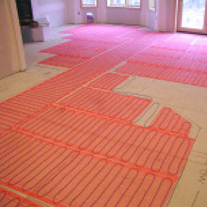
• SunTouch mats come in many different sizes and they can be shaped and used in combinations to warm any room.
• SunTouch power leads and heating elements are fully grounded from one end to the other. The heating elements are reinforced with Aramid fibers and ethylene tetra fluoroethylene (ETFE) insulation.
• SunTouch heating elements are manufactured with a braided twin-wire design and shielded to reduce electromagnetic fields (EMF) to ultra-low levels.
• SunTouch mats are tested to the independently-verified Radiant Electric Emissions Test (REET) standard for use in living areas.
• SunTouch controls are GFCI protected.
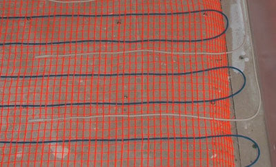
The SunTouch Mat
The heating wire is woven into a special orange fiber to make rectangular mats. These mats are manufactured for 120 VAC and 240 VAC, in 1, 2, and 3-ft. widths.
Mats range from 10 sq. ft. to 160 sq. ft., depending on width, length, and voltage.
Mats of different dimensions must be wired together in parallel (not series) to fill larger areas.
However, they must be the same voltage.
For example, to warm an 80 sq. ft. area, many combinations are possible: two 1′ x 40′ mats; or even a combination of one 2′ x 20′ and one 1′ x 40′. Never combine 120 VAC mats with 240 VAC mats.
SunTouch is a safe and efficient electric floor-warming product for interior applications. It cannot be used for exterior snow melting applications. It is generally intended for installation below tile, stone, and other masonry flooring materials in residential and moderate commercial installations.
SunTouch can be used to heat a room, as well as warm the floor, provided the heat loss of the room falls below the mat’s capabilities. Please refer to specific design information provided for heating applications, especially when installing non-masonry flooring materials.
The designer must determine if the output of the SunTouch is enough heat to match the heat loss of the structure
Anatomy of world class heating wire
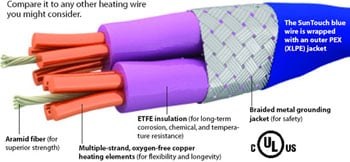
Enlarged cutaway view of the heating wire.
Please refer to your designer if you have further questions regarding the surface temperature you can expect from SunTouch in your particular construction.
NOTE: SunTouch has been tested to the American
Standard Test Method ASTM C627, a standard test method for evaluating ceramic floor tile installation systems using the Robinson-Type Floor Tester.
This test was performed by The Tile Council of America for installation above a concrete slab and above a framed floor.
This testing resulted in a rating of “Moderate Commercial” for normal (non-vehicular) commercial and light institutional use. This would include all (non vehicular) residential use as well.
Never install SunTouch directly below vinyl, carpet, or wood flooring.
SunTouch must be embedded in mortar, per UL requirements. Do not use glues or adhesives. Non-masonry flooring materials such as carpet, vinyl, or hardwood can be installed over SunTouch if the mat is installed in a cement-based or gypsum-based material.
If you have any questions, visit our Web site at www.flooringsupplyshop.com, or call us at 1-877-880 TILE (8453)
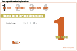
Here’s What You’ll Need:
Determine how many SunTouch heating you need
The primary components of the SunTouch system, depending
on the project requirements, are:
1. SunTouch mat*
2. Floor-sensing thermostat (programmable or non-programmable)*†
3. GFCI breaker (if not part of the thermostat)
4. External contactor (if required)
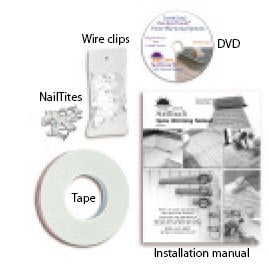
Other items needed:
• SunTouch Installation Kit* (shown below)
• Pneumatic stapler and hot glue gun
• 2-1/8″ deep, 4″ square electrical box for thermostat
• Single-gang “mud” (sheet rock) ring for 4″ square box
• 12-gauge electrical wiring
• LoudMouth monitor*
• Digital ohmmeter (multi-meter)
• Tile installation products (mortar, backer board, tile, etc.)
• 3/8″ x 1/4″ or greater trowel and other tile tools
• Various electrical and construction tools: (wire stripper, screwdriver, chisel, scissors, etc.)
• Insulation (if required per design) Consult with local building authorities, since many areas require that a qualified electrician perform all of the wiring and hookups.
* Items available from SunTouch. All other items are not included and can be purchased locally.
• The SunStat is approved for use in U.S. and Canada, separate from the SunTouch Listed assembly.
READ BEFORE INSTALLING SUNTOUCH
NEVER install SunTouch under carpet, wood, vinyl, or other non-masonry flooring without embedding it in thin-set, thick-set, or self-leveling mortar.
NEVER install SunTouch in adhesives or glues intended for vinyl tile or other laminate flooring. It must be embedded in cement-based ceramic tile mortar.
NEVER cut the heating wire.
NEVER bang a trowel on the mat or heating wire to remove excess mortar from it.
NEVER cut the mats to make them shorter. Only the fiber mesh can be cut to make turns or to help make the mat fit a particular area.
NEVER attempt to repair the heating wire if it is damaged. Call the factory for instructions before proceeding.
NEVER splice one mat heating wire to another mat heating wire to make a longer mat. Multiple mats must be connected in parallel directly to power in a junction box or to the control.
NEVER install one mat on top of another or overlap the mat on itself. This will cause dangerous overheating.
NEVER forget to install the floor sensor.
NEVER install SunTouch in any walls.
NEVER install mats under cabinets or other built-ins, or in small closets. Excessive heat will build up in these small spaces, and the mat can be damaged by fasteners (nails, screws, etc.) used to install built-ins.
NEVER remove the nameplate label from the power leads.
ALWAYS completely embed the heating wire and factory connection in mortar.
ALWAYS enter mat and sensor resistance readings in the Mat and Sensor Resistance Log (page 4) before, during, and after the installation process.
ALWAYS pay close attention to voltage and amperage requirements of the breaker, the control, and the SunTouch mat.
For instance, do not supply 240 VAC power to 120-VAC SunTouch mats or controls.
ALWAYS make sure all electrical work is done by qualified persons in accordance with local building and electrical codes, Section 62 of the Canadian Electrical Code (CEC) Part I, and the National Electrical Code (NEC), especially Article 424, Part IX of the NEC, ANSI/NFPA 70, and Section 62 of CEC Part I.
ALWAYS use copper only as supply conductors.
ALWAYS affix the warning label (included with this manual) to the control cover plate or other location where it will be easily noticed.
ALWAYS seek help if a problem arises. If ever in doubt about the correct installation procedure to follow, or if the product appears to be damaged, the factory must be called before proceeding with the installation.
Inspect the Mat and Sensor
Throughout the installation process, it is very important to take resistance readings of the mat and the floor sensor wire to make sure they have not been damaged.
Use a quality digital ohmmeter (multimeter) able to measure to 20,000 ohms (W) to take these readings. Analog meters (with the moving needle) are not accurate enough for this product.
The LoudMouth™ monitor shown here will help constantly monitor the mat for you during the entire installation. (include with our kits)
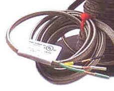
Record the information from this nameplate label into the Mat and Sensor Resistance Log.
Leave the nameplate label attached to the power leads for later inspection

The LoudMouth monitors the heating wire during the entire installation process. If the mat is cut or damaged during installation, this device sounds an alarm.
The LoudMouth will prevent burying a damaged wire below hardened mortar and tile or stone.
Essential Product and Warranty Information
Do not remove the nameplate label from the power leads (see photo at above).
Record the mat serial number, mat size, voltage, and resistance range printed on this label into the resistance log below for each mat and sensor.
To retain the Limited Warranty, these items and the following measurements must be recorded, as well as all steps of this manual followed.
Refer to the Limited Warranty now for complete requirements.
Mat and Sensor Resistance Log
|
Mat 1
|
Mat 2
|
Mat 3
|
|
| Mat Serial Number | |||
| Mat Model | |||
| Mat Voltage | |||
| Mat Resistance Range |
OUT OF THE BOX BEFORE INSTALLATION (ohms)
| Mat black to white | |||
| Mat black to green | |||
| Mat white to green | |||
| Sensor Wire |
AFTER MAT AND SENSOR ARE FASTENED TO FLOOR (ohms)
| Mat black to white | |||
| Mat black to green | |||
| Mat white to green | |||
| Sensor Wire |
AFTER FLOOR COVERINGS ARE INSTALLED OVER THE MAT (ohms)
| Mat black to white | |||
| Mat black to green | |||
| Mat white to green | |||
| Sensor Wire |
RETAIN THIS LOG TO RETAIN THE WARRANTY!- DO NOT DISCARD!
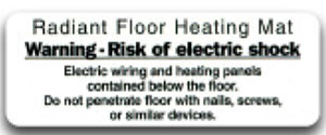
This electric radiant heating warning label must be placed near or on the face of the control.
Measurements
At the very least, take resistance readings
(1) before beginning the installation,
(2) after the mat and sensor are fastened to the floor, and
(3) after floor coverings are installed.
It is highly recommended frequently during tile installation to avoid burying a damaged heating wire or defective sensor.
Checking for breaks
Measure resistance between the black and white leads (black and blue leads for 240-V mats) and record below.
This resistance should be within the range shown on the nameplate label. Measure between the lead wires of the floor sensor.
This resistance varies according to the temperature sensed in the tip. The sensor resistance table at lower left provides approximate values for comparison.
A cut or break in the wire is indicated by a resistance of “infinite” ohms (no continuity, or “OL” for “open line”).
Checking for short-circuits
Measure mat resistances between the black and green leads. Record below.
This measurement should be “infinite” ohms (no continuity or “OL” for “open line”). A cut or pinch in the heating wire is normally indicated by a resistance value greater than zero and less than the mat resistance
mat resistance If the resistance is not correct, contact the factory for further instructions. If the
heating wire has been cut or damaged, quickly clean up the damaged area and
contact the factory for further instructions.
The floor temperature attainable is dependent on how well the floor is insulated, the temperature of the floor before start up, and in the case of un insulated slab applications,
the thermal drain of the underlying materials.
Please refer to your designer if you have further questions regarding the surface temperature you can expect from SunTouch WarmWire in your particular construction. Please see Phase 9: “Install Insulation”
Phase 1. Electrical Rough-in
STEP 1.1: Install GFCI Breaker (Over current Protection)
The SunTouch mat must be protected by a ground fault circuit interrupter (GFCI).
This can be done either by the internal GFCI in the SunTouch SunStat (as long as it directly controls the mat) or an indicating-type GFCI circuit breaker.
This GFCI serves as a local disconnect.
Note: Follow all local building and electrical codes.
Note: It is possible to branch from an existing circuit, but this is not recommended.
Please consult with a qualified electrician to determine if the circuit can handle the load and if the circuit is GFCI-protected.
The size of the breaker is determined by the total square footage of heating mat. (Depending on local codes, you may need multiple breakers for systems larger than 20 amps.)
Typical Amperage Requirement:
120 VAC SunTouch mats: 0.1 amps per sq. ft., or 10 amps per 100 sq. ft. of mat.
240 VAC SunTouch Mats: 0.05 amps per sq.ft., or 5 amps per 100 sq.ft. of mat.
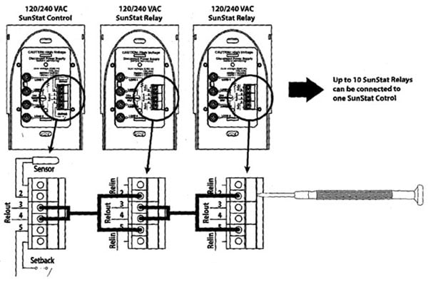
STEP 1.2: Install Secondary Skwe Unit (SunStat Relay)
Depending on the amperage require ments of the mat(s), an secondary slave unit (SunStat Relay) may be required. See page 17 for connection diagram.
Do not load the SunStat control with more than 15 amps. Be sure to protect this contactor circuit with a GFCI breaker.
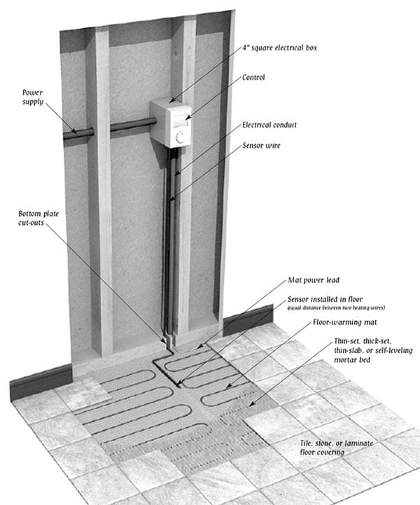
STEP 1.3: Install Electrical Boxes
Thermostats are usually located near the power leads. However, they can be located almost anywhere, because the power leads and the sensor wire can be routed to electrical junction boxes and extended to a location outside the heated room (such as a utility room or basement).
Thermostat: Install a 4″-square, 2-1/8″ deep electrical box with a 1-gang mud ring.
Electrical boxes should be located on interior walls, typically 60″ from the floor, according to NEC or other local code requirements.
Note: The SunStat sensor wire can be extended up to a maximum of 50′, if necessary.
STEP 1.4: Bottom Plate Work
Drill or saw holes at the bottom plate as indicated at right. One hole is for routing the power leads or conduit and the other is for the thermostat sensor.
These holes should be directly below the electrical box(es) (see photos).
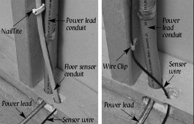
STEP 1.5: Install Power Lead Conduit and Thermostat Sensor
Power Lead Conduit: The shielded power lead can be installed with or without electrical conduit depending on code requirements. In either case, remove one of the knock-outs in the 4″ box to route the lead. If electrical conduit is not required by code, install a wire collar to secure the leads where they enter the box.
If conduit is required by code, install 1/2″ (minimum) conduit from the bottom plate up to the electrical box. For multiple power leads (multiple mats) install 3/4″ conduit, which will accommodate multiple power leads.
Thermostat Sensor: A floor sensor comes with our SunStat control. It can be installed in a conduit separate from the electrical power lead although this is not necessary.
Open a second knock-out in the bottom of the thermostat box. Feed the sensor (and conduit) through the knock-out, down through the cut-out in the bottom plate, and out into the floor where the heating mat will be installed. If you have the thermostat and sensor, install the sensor now, but wait to install the thermostat until after the mat is installed
Note: The sensor is located in the thermostat packaging.
STEP 1.6: Rough-in Wiring
Install appropriate electrical wire (conductor) from the power source and breaker protection to the thermostat following all codes.
Leave 6″- 8″ extra wire at the thermostat box. Refer to the Typical Wiring Diagrams at the end of this manual for help.
| Mat Amperage Requirements 120 Volt |
| 120 VAC, 1-ft.-wide mats | 120 VAC, 2-ft.-wide mats | 120 VAC, 3-ft.-wide mats |
|
Mat Size
|
Sq Footage
|
Amp Draw
|
Mat Size
|
Sq Footage
|
Amp Draw
|
Mat Size
|
Sq Footage
|
Amp Draw
|
|
1′ x 10′
|
10 sq.
|
1.0
|
2′ x 5′
|
10 sq.
|
1.0
|
|||
|
1′ x 15′
|
15 sq.
|
1.5
|
2′ x 7′-6″
|
1.5
|
3′ x 5′
|
15 sq.
|
1.5
|
|
|
1′ x 20′
|
20 sq.
|
2.0
|
2′ x 10′
|
20 sq.
|
2.0
|
3′ x 6′-8″
|
20 sq.
|
2.0
|
|
1′ x 25′
|
25 sq.
|
2.5
|
2′ x 12′-6″
|
25 sq.
|
2.5
|
3′ x 8′-4″
|
25 sq.
|
2.5
|
|
1′ x 30′
|
30 sq.
|
3.0
|
2′ x 15′
|
30 sq.
|
3.0
|
3′ x 10′
|
30 sq.
|
3.0
|
|
1′ x 35′
|
35 sq.
|
3.5
|
2′ x 17′-6″
|
35 sq.
|
3.5
|
|||
|
1′ x 40′
|
40 sq.
|
4.0
|
2′ x 20′
|
40 sq.
|
4.0
|
|||
|
2′ x 22′-6
|
45 sq.
|
4.5
|
3′ x 15′
|
45 sq.
|
4.5
|
|||
|
2′ x 25′
|
50 sq
|
5.0
|
||||||
|
2′ x 30′
|
60 sq.
|
6.0
|
2′ x 20′
|
60 sq.
|
6.0
|
|||
|
2′ x 35′
|
70 sq.
|
7.0
|
||||||
|
2′ x 40′
|
80 sq.
|
8.0
|
|
Mat Amperage Requirements 240Volt
|
|
240 VAC, 2-ft.-wide mats
|
240 VAC, 3-ft.-wide mats
|
|
Mat Size
|
Sq Footage
|
Amp Draw
|
Mat Size
|
Sq Footage
|
Amp Draw
|
|
2′ x 10′
|
20 sq.
|
1.0
|
|||
|
2′ x 15′
|
30 sq.
|
1.5
|
3′ x 10′
|
30 sq.
|
1.5
|
|
2′ x 20′
|
40 sq.
|
2.0
|
3′ x 13′-4″
|
40 sq.
|
2.0
|
|
2′ x 25′
|
50 sq.
|
2.5
|
3′ x 16′-8″
|
50 sq.
|
2.5
|
|
2′ x 30′
|
60 sq.
|
3.0
|
3′ x 20′
|
60 sq.
|
3.0
|
|
2′ x 35′
|
70 sq.
|
3.5
|
|||
|
2′ x 40′
|
80 sq.
|
4.0
|
|||
|
2′ x 45′
|
90 sq.
|
4.5
|
3′ x 30′
|
90 sq.
|
4.5
|
|
2′ x 50′
|
100 sq.
|
5.0
|
|||
|
2′ x 60′
|
120 sq.
|
6.0
|
3′ x 40′
|
120 sq.
|
6.0
|
|
2′ x 70′
|
140 sq.
|
7.0
|
|||
|
2′ x 80′
|
160 sq.
|
8.0
|
Phase 2. SunTouch Installation
STEP 2.1
Select Type of Construction
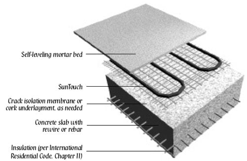
Choose the best thin-set, thick-set, or self leveling mortar installation detail for your application. Consult with building professionals and/or TileDepot personnel for specific details concerning proper installation.
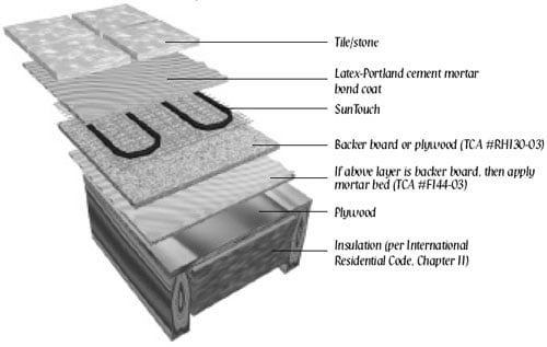
1. THIN-SET MORTAR OVER FRAMED FLOOR
(Dry-set or latex cement mortar; TCA #F144-03; RH130-03)
2. THIN-SET MORTAR OVER SLAB
Dry-set or latex cement on slab; TCA #RH115-03)
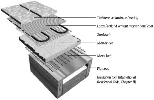
3. THICK-SET CEMENT MORTAR METAL LATH
(Cement mortar metal lath; TCA #145-03)
STEP 2.2
Floor Preparation
The floor must be completely swept of all debris including all nails, dirt, wood, and other construction debris.
Make absolutely sure there are no objects on the floor that might damage the SunTouch wire.
STEP 2.3
Study the Factory-supplied Items and the Design
Make sure all of the correct materials have been purchased.
A general list of materials is found at the beginning of this manual.
Study the design carefully before installation.
Review the thermostat location and where the mat begins and ends, as well as the general layout pattern.
Do not cut the wire or shorten the mat to make it fit the space. Doing so will cause dangerous overheating and will void the warranty!
STEP 2.4
Mortar and Thin-Slab Applications
SunTouch can be installed in two types of construction applications:
1. Thin-set or thick-set mortar beds (3/8″-1″).
2. Self-leveling mortar beds (1/4″-1/2″).
No matter the application, always install SunTouch before installing mortar or cement.
Do not lay SunTouch in wet mortar.
We strongly recommend installing tile and stone flooring according to manufacturer’s recommendations, TCA guidelines, and ANSI specifications.
If installing non-masonry floor coverings, such as hardwood, vinyl, laminate or carpet, follow industry and manufacturer’s recommendations.
If installing non-masonry coverings, the best method is cover the SunTouch in a self leveling mortar (illustrations #5 and #6)
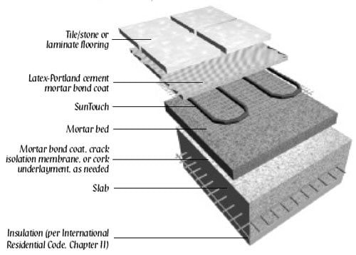
4. THICK-SET MORTAR BED OVER SLAB
(Cement mortar bonded; TCA #F112-03)
SELF-LEVELING APPLICATIONS
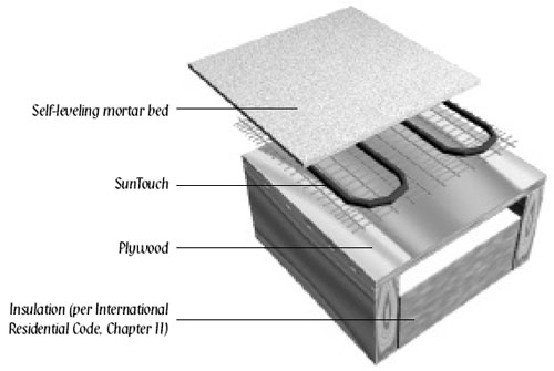
5. SELF-LEVELING MORTAR OVER FRAME FLOOR
Mortar Applications:
There are two types of thin-set and two types of thick-set mortar applications illustrated on these pages.
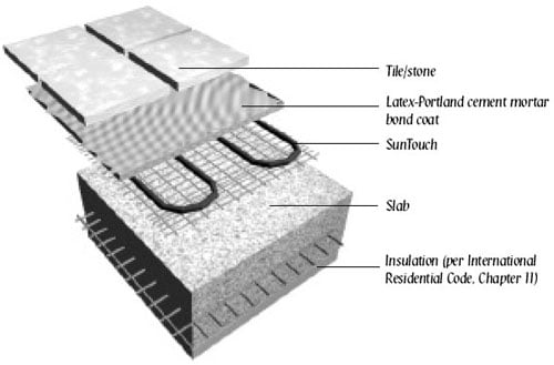
A . If backer board or plywood sheeting is used to strengthen the floor, or if the mat will be placed directly onto the slab, install SunTouch in the thin-set mortar bond coat above these materials. See illustrations #1 or #2.
B . If a thicker mortar bed is used to strengthen the floor, SunTouch can be installed in either the mortar bed (dry-set) or in the mortar bond coat directly below the tile or stone. See illustrations #3 or #4.
In this application, SunTouch is generally installed above the self-leveling mortar in a thin-set bond coat.
If you use plastic lath instead of the typical metal lath, the SunTouch can be installed in the self-leveling mortar bed.
CAUTION:
If metal lath is used in the mortar bed, do not allow the SunTouch to come in direct contact with the lath because this could damage the wire.
6. SELF-LEVELING MORTAR OVER SLAB ON GRADE
Self-leveling Mortar Applications:
There are only two approved methods of installing cement based, self-leveling mortar beds over SunTouch.
One for framed floor construction and one for slab construction ( illustrations #5 & #6).
These are appropriate applications if installing engineered wood, vinyl, laminate, or carpet floor coverings.
Attach the SunTouch to the subfloor or slab, then pour self-leveling mortar 1/4″ to 1/2″ thick according to manufacturer’s specifications.
Install floor covering after the mortar has cured.
Special Precautions
Isolation Membrane: Install the SunTouch above the membrane, whenever possible, unless recommended otherwise by the membrane manufacturer.
Insulation: Do not install rigid insulation directly above or below backer board or mortar.
If possible, install insulation as shown in diagrams. Insulation dramatically enhances the performance and efficiency of floor-warming systems.
Mosaic Tile: When installing mosaic tile, we recommend a two-step process. First embed the SunTouch in a thin mortar bed (1/4″–3/8″), then thin-set the mosaic tile according to typical practice.
Expansion Joints: Do not install heating mats through an expansion joint. Install mats right up to the joint, if necessary, but not through the joint. Illustrations #5 and #6 show the best method if you are installing non-masonry floor coverings.
Step 2.5
SunTouch Installation
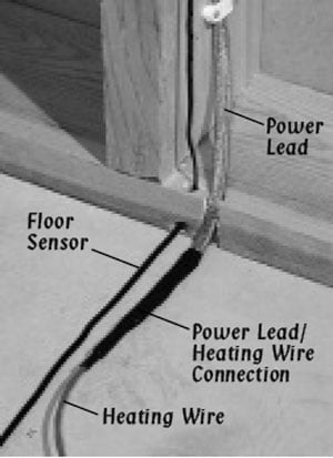
Position the power leads near the thermostat.If this is not possible, then route the power lead through a wall and/or floor over to the location of the thermostat (follow all electrical/ building codes using electrical conduit and boxes).
In all applications, double-sided tape can be used to affix SunTouch to the substrate. However, if installing SunTouch over backer board or plywood,pneumatic stapling can be faster.
Begin the installation by rolling out the mat according to the plan. At each turn or bend, stop and stretch the mat tightly to pull out the slack. Then affix the mat to the floor using double-sided tape or staples.
When using double-sided tape, apply it to the floor on 2′ centers, or more, as necessary, depending on jobsite conditions.
The tighter the mat, the simpler the thin-setting will be.
The floor must be clear of debris for the tape to stick. Firmly rub the white, paper side of the tape before pulling off the paper. This will ensure a strong bond between the tape and the floor. Cover approximately 10 sq. ft. at a time.
Use short pieces as necessary at the corners.
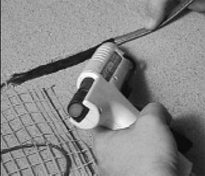
When using pneumatic staples, we recommend 3/8″ x 1/4″ chisel point staples. Initially attach the SunTouch mat every 2′ to 3′ on either side of the mat in the “valleys” between the heating wires as shown at left. By doing so it will be easier to pull up the mat and reposition, if necessary. When satisfied with the layout, go back and staple on 1′ centers at either side in the “valleys” between the wires. Proceed slowly and be very careful not to staple the heating wire.
Cut or remove the orange weave as necessary to make turns. Do not tack or staple the heating wire.
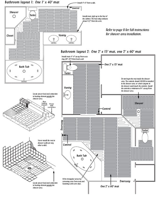
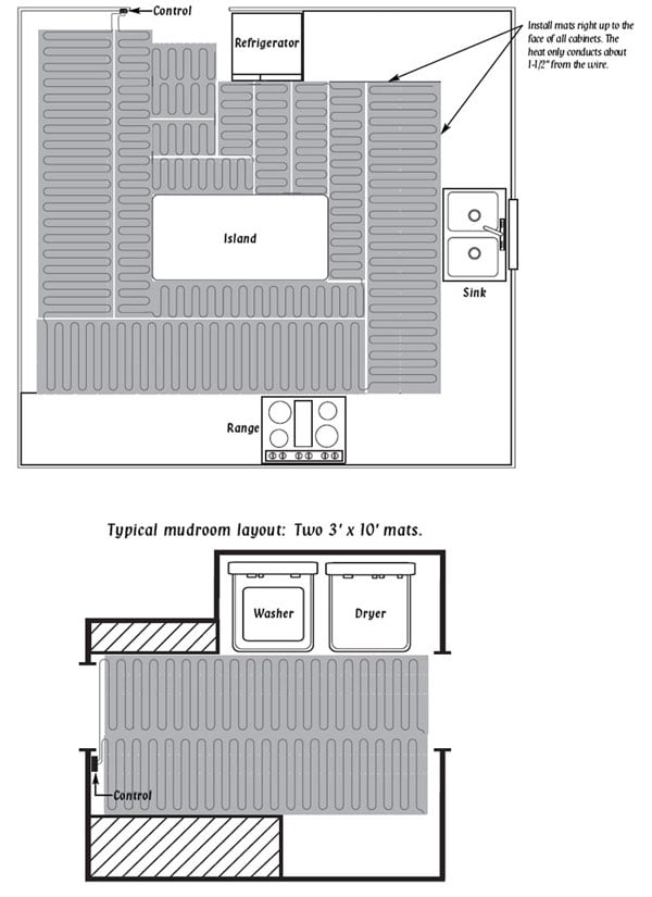
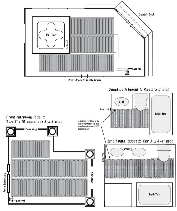
Install the SunTouch approximately 4″ – 6″ away from walls, showers, tubs, toilets, drains, etc., as shown in this section and the Appendix. Install in-line with vanity and counter areas.
This is because you want to make sure to get heat right up to the face of the cabinet so that toes are kept warm. Install roughly 18″ – 20″ from back wall in toilet area. (See “PROTECT THE MAT FROM TRAFFIC” section for details).
Do not leave gaps between the mats. The heat will conduct only 1″–2″ from the heating wire. SunTouch should be installed continuously across the floor as shown in the diagrams in this manual. Never install mats in a fashion causing the heating wires to be any closer than 2″ from each other.
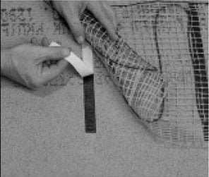
Secure mat to floor using double-sided tape.
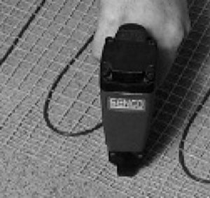
…or staple mat in the “valleys”.
Step 2.6
Shower Installation
SunTouch can be installed in shower areas, but there are several precautions that must be observed (see “Appendix 3. Example Layouts” for more details).
1. Never install SunTouch in shower walls (or any other wall).
2. Never make a field splice to mats installed in shower.
Do not attempt to repair or modify the mat in any way; serious hazard could result.
3. Embed mats in mortar and install only under tile, stone, brick, or other masonry surface, per this instruction manual.
4. Never begin the mat in the shower. The connection between the power lead and the heating wire must be fully embedded in mortar and located at least 1′ away from shower openings and other areas normally exposed to water.
5. Mat controls must be located at least 4′ away from shower openings such that they cannot be exposed to water or touched by a person in the shower area.
Either hot glue power lead into chiseled path . . .
Step 2.7
Power Lead and Factory Connection Installation
Power Lead Installation: The power lead is thicker than the SunTouch mat. If thin-setting over backer board or slab, chisel or saw a groove to recess the power lead to the level of the SunTouch. Use hot glue to secure the power lead in the groove. Or end the power lead at the floor and run just the heating wire to the beginning of the mat.
Do not damage the power lead electrical shock could result when the mat is energized.
Factory Connection Installation:
Depending on the thickness of the mortar bed, you may need to chisel under the factory connection in order to recess the connection.
Be extremely careful not to damage the heating wire or connection. A dab of hot glue will hold the connection in place.
Step 2.8
Thermostat Sensor Installation
A sensor should be installed in the floor and routed up the wall as described in Step 1.4.
Simply tuck it under the mat or weave it in between two heating wires.
The sensor should extend approximately 6″–12″ into the mat as shown on “Phase 4. Final Wiring” section. Be careful not to locate the sensor near other heating sources such as a heating duct below the floor
C A U T I O N !
PROTECT THE MAT FROM TRAFFIC
If the floor covering is not immediately installed, protect the SunTouch mat by covering it with corrugated box material or plywood. Keep traffic to a minimum on the installed mat.
Step 2.9
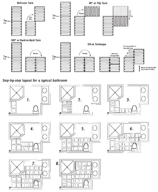
Mat Turns and “Fill-in” Techniques
This section contains some of the common turns and techniques used to layout around corners, angles, and built-ins.
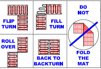
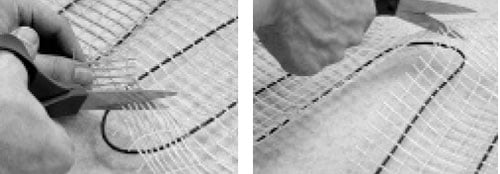
Carefully cut the orange woven mat to effect turns. Never cut, nick, or otherwise damage the heating wire.
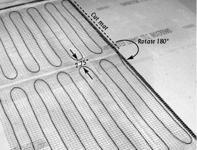
180° or Back-to-Back Turn.
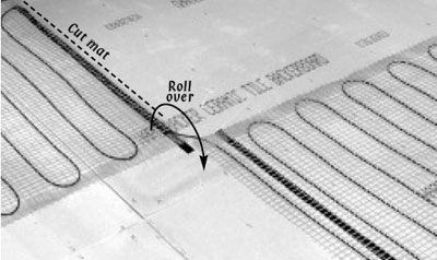
Roll-over Turn.
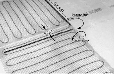
90° or Flip Turn.
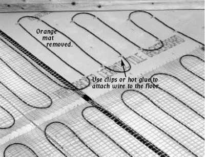
Fill-in Technique.
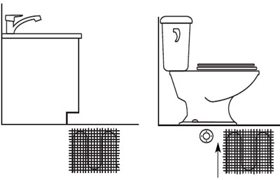
Note: Install mat right up to the face of the cabinet as shown above.
Note: Mat can be installed under tile to within 4″–6″ from the front of the wax ring, and can slightly underlay the foot of the toilet if need be (approximately 20″ from wall).
Phase 3. Final Floor Installation
We recommend working with professional flooring installers to make sure proper materials are used and proper installation techniques are followed.
Please note, the SunTouch installation video is not a flooring installation video – it only covers the installation of SunTouch floor-warming mats.
Use a digital ohmmeter to check the resistance of the mat(s) and sensor(s) before, during and after the installation of any floor coverings. Record the readings in the Mat and Sensor Resistance Log (above), continuing to check for short circuits caused by nicks or pinches.
If possible, take photographs of the mat installation before installing the flooring.
Warning: Never bang a trowel on the mat or the heating wire to remove excess mortar from the trowel. This could sever the heating wire.
When installing tile or stone over SunTouch, we highly recommend Tile Council of America (TCA) guidelines or ANSI specifications as a minimum standards of installation.
We recommend latex-modified or epoxy-modified mortar and grout, instead of water-based multipurpose materials.
Select the proper size trowel for the installation of tile or stone.
We recommend a minimum 3/8″ x 1/4″ trowel. This trowel works best for most 1/4″ tile.
Note: Mortar beds thicker than 3/8″ work fine with the performance of the system; they just take a little longer to heat up.
When installing floor coverings other than tile or stone, follow industry and/or manufacturer’s recommendations.
Also, make sure nails, screws, or other fasteners do not penetrate the floor in the area of SunTouch. The wire can easily be damaged by fasteners penetrating the floor.
All floor coverings must be in direct contact with the cement-based material that encase the SunTouch. Do not elevate the floor above the concrete or mortar mass below. For instance, do not install 2″ x 4″ wooden nailers (sleepers) on top of a slab for the purpose of attaching hardwood. This 1.5″ air gap will drastically reduce the output of the heated slab. For this reason, “floating”
wood/laminate floors work much better than strip hardwood flooring.

Keep LoudMouth monitor connected during the installation of flooring materials.
This electric radiant heating warning label must be placed near or on the face of the control.
Bottom plate/sensor detail. Simply “weave” the sensor into the mat, or you may prefer to use a clip.
Phase 4. Final Wiring
Step 4.1
Install the Controls
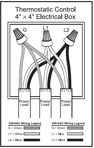
Install the floor-sensing thermostat in the 4″ square electrical box, according to the installation sheets provided with the thermostat. Connect the mat power leads, floor sensor, and power supply wiring as shown in this manual (Appendix 4.) or in the thermostat installation sheets.
If using multiple mats, route all power leads up through the electrical conduit and into the 4″ square thermostat box or separate junction box.
Wire the leads in parallel (not series) – black-black, white-white, and green-green, or for 240V systems; black-black, blue-blue, green-green.
Then wire a short “pig-tail” (of correctly sized wire for the load) over to the thermostat.
Use the 1-gang mud (sheet rock) ring to mount the thermostat to the electrical box.
Appendix 1. Installation Overview
Appendix 2. Mat Turns and Fill-in Techniques
Types of turns
Example Layouts
Typical kitchen layout: One 2′ x 25′ mat, one 1′ x 35′ mat
Sunroom/porch layout example: Two 3′ x 6′ -8″ mats, one 3′ x 10′ mat
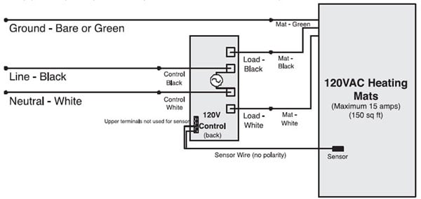
Appendix 4. 120V Control Wiring Diagrams
Typical Electrical Wiring Diagram with SunStat Control (120/240VAC)
Dedicated 120 or 240VAC, 20-amp (maximum) circuit.
Typical Electrical Wiring Diagram with SunStat Controller and Contactor (120V)
Dedicated 120 or 240VAC, 20-amp (maximum) circuit.
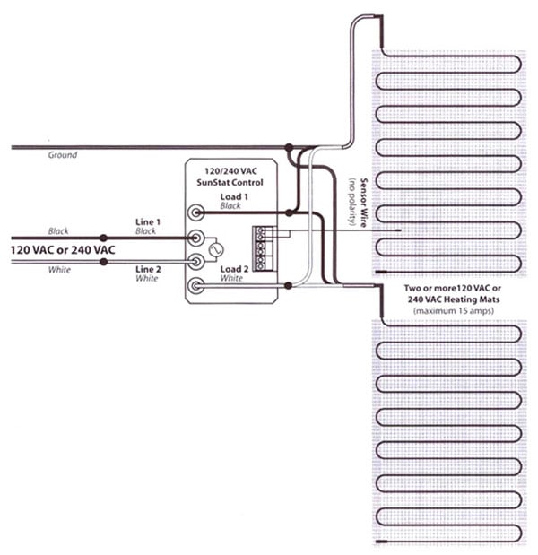
Appendix 4. 240V Control Wiring Diagrams
Typical Electrical Wiring Diagram with SunStat Controller (240V)
Dedicated 240-V, 20-amp (maximum) circuit.
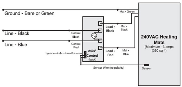
Diagram for connection of signal wire between SunStat Control and Relays
Dedicated 240-V, 20-amp (maximum) circuit.
All electrical work must be done by a qualified licensed electrician with local building and electrical codes, and the National Electrical Code (NEC) especially Article 424, part IX of the NEC, ANSI/NEPA70 and Section 62 of CEC Part 1.
Appendix 5. Troubleshooting Guide
If problems arise with the SunTouch floor-warming mat or its related electrical components,
please consult this troubleshooting guide. If not qualified to perform electrical work, it is highly recommended that a qualified, licensed electrician be hired.
Any electrical troubleshooting work should be performed with the power removed from the circuit, unless otherwise noted
|
Problem
|
Possible Cause
|
Solution
|
| Mat resistance measurement is outside the range printed on the nameplate label. | An analog ohmmeter (using a moving needle) was used to take the reading. | Obtain a digital ohmmeter able to read 0 to 20,000 ohms and re measure the resistance. |
| If measurement shows an open or short circuit, the heating wire has been damaged. | Record resistance between all wires and contact the manufacturer. | |
| If measurement is just a little low or high, room temperature has affected the resistance. | Make the room temperature 75°-85°F, or contact the manufacturer. | |
| The resistance measurement could be from more than one mat wired in series, or wired in parallel. Either will provide false resistance readings. | Make sure resistance measurements are for only one mat at a time. When connecting more than one mat to the control, multiple mats must be wired in parallel (i.e., black to black, white to white). | |
| The ohmmeter may be set to the wrong scale. For instance, the 200 K ohms scale measures up to 200,000 ohms. | The ohmmeter should typically be set to the 200 ohms scale, with the exception of mats having a rating above 200 ohms on their nameplate label. If the resistance reading is outside the range printed on the nameplate label, contact the manufacturer. | |
| Floor is not getting warm. | Mat has been damaged. | Measure mat resistance. Check for both “open circuit” and “short circuit” as detailed earlier in this manual. If damaged, record resistances between all wires and contact the manufacturer. |
| GFCI has tripped, indicated by a light on the control. Light may be labeled “GFI”, may be below the words “Stand by”, or on the button labeled “Test”. | Check for loose wire connections. Reset the GFCI on the control or circuit breaker. If it trips again, check for a short circuit in the mat as detailed earlier in this manual. If mat is damaged, record resistance between all wires and contact the manufacturer. If mat is not damaged, replace the GFCI control. Also see “GFCI conflicts” below. | |
| Incorrect voltage supplied, or mismatched electrical components used. | Measure “line” voltage, then measure “load” voltage. Both 120-V mats and controls have black and white leads. 240 V mats have black and blue leads, and 240-V controls have black and red leads. | |
| Concrete slab floor. | Surface temperatures rise slowly in a slab. If, after 5 to 8 hours of heating, the floor is not warmer to the touch, check for mat damage (see “Mat has been damaged” above). Measure “load” voltage/amperage to mat. | |
| Floor heats continuously. | Mats are wired in “series” or “daisy” chained” (end-to-end). | Multiple mats must be connected in “parallel” (or black-to black, white-to-white). |
| Sensor is loose or broken. If control has a digital display, it may indicate “LO”. | SunTouch controls have a floor sensor. Pull the sensor wires loose from the control and reinsert them. If this does not solve the problem, measure resistance across the sensor wires. For a SunTouch control the resistance should be between 17,000 ohms (at 55°F) and 8,000 ohms (at 85°F). See sensor wire resistance values in this manuel | |
| Incorrect wiring. The control was “bypassed” when it was wired to the power supply. | Make sure wiring connections are correct. Consult the wiring diagram on the back of the control, the instructions that came with the control, or the wiring diagram in this manual. | |
| Defective control. | Return control to dealer for replacement. | |
| Floor temperature shows “HI” or may show temperature over 100°F. | Floor sensor is not wired properly, or is located incorrectly. | Make sure only one floor sensor is connected to the control. Also see “Sensor is loose or broken” above. |
| Control is not working correctly. | If a programmable control, the programming may be incorrect. | Carefully read and follow control programming instructions. |
| Incorrect voltage supplied, or mismatched components used. | Test voltage, verify parts. See “Incorrect voltage supplied” above. | |
| Floor sensor is not wired properly, or is not working properly. | Make sure only one floor sensor is connected to the control. Also see “Sensor is loose or broken” above. | |
| Loose connection(s) on line side and/or load side of control. | Remove and reinstall the wire nuts at each connection. Make sure the wire nuts are tight. Check all connections back to the breaker. | |
| Defective control. | Return control to dealer for replacement. | |
| Control is not working at all. | No power is supplied. | Check circuit breaker. Measure voltage at the control. Check all connections between breaker and control. |
| Floor sensor is not wired properly, or is not working properly. | Make sure only one floor sensor is connected to the control. Also see “Sensor is loose or broken” above. | |
| Defective control. | Return control to dealer for replacement. | |
| GFCI conflicts and false-trips. | More than one GFCI on the circuit. | GFCI units will sometimes trip when there is nothing wrong with the equipment on the circuit, but when there is more than one GFCI. Reroute power to avoid having more than one GFCI on the circuit. |
| An electric motor or a ballasted light source is sharing the circuit with the mat. | Electric motors and other electrical devices can cause a GFCI to false-trip. Run a dedicated circuit to the floor warming system. |
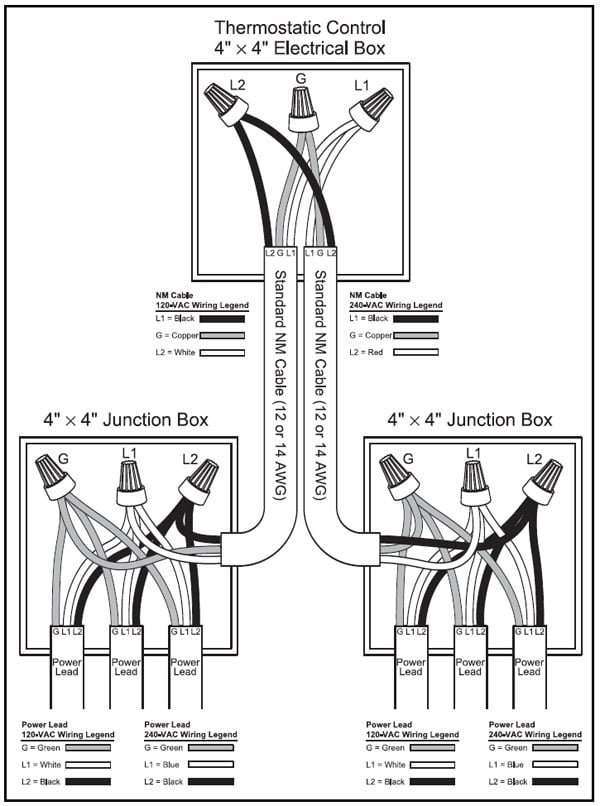
Appendix 6. Connecting Multiple Mats
NOTE: The thermostatic control is not shown in these diagrams in order to simplify them.
These diagrams are given only as examples of how to properly connect multiple mats.
Care must be taken not to overfill a box.
Be sure to use wire nuts that are the correct size for the connections being made.
Follow all codes for wiring. If in doubt, consult an electrician
Enjoy your new SunTouch Mat floor-warming system!
Click here for SunTouch VIDEO Library
SunTouch vs. Product A – SunTouch vs. Product B
SunTouch Floor Heating Mat Links
SunTouch Mats Spec and installation – SunTouch Mat Specification – Underfloor Spec and Installation
SunTouch Floor Heating Spool Links
SunTouch WarmWire Installation Guidelines – SunTouch WarmWire Strap – WarmWire Installation Guidelines – WarmWire Order Instruction and Information
Heating Controls Links
Programmable SunStat Spec – Owner’s Manual Programmable 500670-SB – Owner Manual Non Programmable 500675
– SunStat Non Programmable Spec – SunStat Relays Control – LoudMouth Operating Instruction
Misc SunTouch Links
SunTouch 25 year Limited Warranty – EMF Electromagnetic fields – Frequently Asked Questions – Repair Heating Wire – Suntouch Low Price Guarantee