Owner’s Manual SunStat Relays Control 500680
By SunTouch® A division of Watts Water Technologies, Inc.
![]()
Your new SunStat Relay is designed to control the voltage to either a 120VAC or 240VAC resistive floor warming system. It must be driven by a SunStat thermostat to operate.
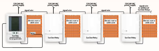
SunTouch’s new SunStat™ Relays System is specially designed for large floor heating applications exceeding 15 amps. Here’s how it works:
Relays connect directly to SunStat thermostats for simple, elegant control of larger system
SunStat Relays don’t require a special “master thermostat”, as before with the older version, this new Relays are dual voltage 120 VAC or 240 VAC, have a 15-amp capacity, and on/off switch and GFCI and test light.
It’s possible to control over 1500 sq. ft. of electric floor warming using 120 VAC and cover 3,000 VAC sq. ft floor warming mats or cables.
Make sure you are qualified and are familiar with house wiring. This is a line voltage device that could cause serious injury or damage if improperly installed.
1. Preparation
1. Unpack your Relay and make sure everything is in good condition:
- Relay
- Small screwdriver
- Mounting screws
- Wire nuts for wiring connections
If any parts are missing or damaged, contact the store where you purchased this relay. Do not install a damaged part
2. Gather the following tools and supplies:
- Phillips screwdriver, hole saw
- Wire strippers, “fish tape”, other electrical tools
- Electrical box for relay:
a. If you are connecting to power leads from only 1 or 2 floor warming systems, you may use a single-gang, 31⁄2 inch deep box.
b. If you are connecting to power leads from 2 or 3 floor warming systems, use a 4x4x21⁄8 inch or deeper box (not a 2-gang box) when your wall studs are still exposed. Install a single-gang “mud-ring” cover on the box before installing drywall materials.
c. For more than 3 floor warming systems or other layouts, you may need to install a junction box. See the installation instructions for your floor warming system for more information.
ALWAYS: Wire all circuits as Class 1, Electric Light and Power Circuits.
ALWAYS: Wire all circuits with insulation rated 600V minimum.
ALWAYS: Mount this control only to a grounded metallic box or a nonmetallic box.
ALWAYS: Use power supply wires suitable for at least 90°C.
CAUTION: High voltage – disconnect power supply before servicing
2. Installation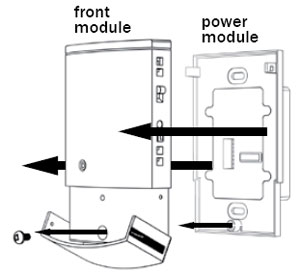
Remove the Thermostat Face
1. Remove the Front Module from the Power Module by opening the door and loosening the screw.
2. Pull outward near the bottom on the Front Module and lift off.
Prepare the Wiring
1. Find a location for your Relay. It is suitable for indoor use only, on insulated or uninsulated walls. Normally it works best at about 41⁄2 feet to 5 feet above the floor on an inside wall. However, you may place it in any area where airflow is not restricted, such as a large utility closet. Avoid placing it inside a cabinet or closet that can confine heat. Avoid placing it near other heat sources such as hot-water piping, heat duct, wall-mount lighting, and direct sunlight to help prevent adversely affecting the control.
2. Turn off the power to the floor warming system at the main circuit panel before doing any electrical work.
3. A qualified electrician should run a dedicated circuit from the main circuit panel to the control location.
4. If a dedicated circuit is not possible, you may tap from another circuit in the room. Make sure there is enough load capacity (amps) to handle the addition of your floor warming system, and that it is NOT wired in series with any other device, including other GFCIs.
5. The circuit breaker in the main circuit panel should be 15 amps maximum for a floor warming system totaling 12 amps or less. For larger systems up to 15 amps, use a 20 amp maximum circuit breaker. Never exceed 15 amps on this thermostat..
6. Pull the power supply wiring into this box, leaving about 6 inches of wire.
7. Pull the power lead wires from your floor warming system up the wall, into this box.
8. Mount the electrical box.
Connect Power Wires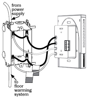
1. Match and connect the two wires marked “LINE1” and “LINE2” to the power supply wires using the wire nuts provided.
2. Gently tug on the wires to make sure they are secure, otherwise a wire could loosen and cause failure.
3. Over wrap the wire nuts with electrical tape to better secure them to the wires.
4. Match and connect the two wires marked “LOAD1” and “LOAD2” to the floor warming system lead wires and secure these wires the same way.
5. Connect the house ground wire to the green lead wire(s) of your floor warming system.
CAUTION: Before continuing, make sure your power supply voltage matches the voltage rating of your floor warming system.
Connecting 240V to a 120V floor warming system will cause overheating and damage to the system and may damage the control, other wiring, floor coverings, etc.
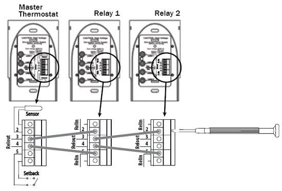
Connect Signal Wires From Thermostat
1. Pull 2-conductor wire, size 18- to 24-gage, through the wall from the SunStat thermostat into this electrical box.
2. Connect the wire ends into the “RELIN” terminals(2 and 5) and tighten the screws (observe polarity). See diagram below. Connect Signal Wires to Other SunStat Relays You may drive up to 10 SunStat Relays with one master SunStat thermostat.
1. Connect 2-conductor wire, size 18- to 24-gage, into the “RELOUT” terminals(3 and 4) of the first Relay.
2. Pull this wire through the wall to the next Relay and connect to its “RELIN” terminals(2 and 5).
3. Repeat this process for additional SunStat Relays.
Mount the Relay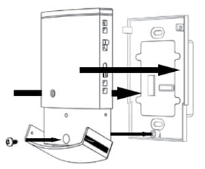
1. Carefully fold and press the wires back into the electrical box. Do not use the control to push them in, as this may cause connections to loosen and possible failure.
2. Secure the Power Module into the box with the mounting screws provided.
3. Carefully snap the Front Module onto the Power Module.
4. Tighten the screw.
5. Switch on the power at the main circuit panel.
NOTE to contractors: After installing the thermostat, be sure to:
- a. Switch on the relay(s)
b. Do a Quick Setup of the master thermostat (see instructions for your SunStat thermostat)
c. Temporarily override the thermostat setpoint temperature, making sure it signals this Relay to begin heating for a few minutes
d. Test the GFCI (section 3)
3. Operation
On/Off Switch 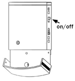
Your SunStat Relay should be turned off when it is first installed.
1. Slide the on/off switch to the upper position, turning the control on. A green light will show on the front if power is applied. If the light is amber, it indicates power is applied to the floor warming system.
2. To turn the control off anytime, slide the on/off switch to the lower position. No heating will occur.
Test the GFCI
To make sure the GFCI is operating, test it after it is installed and once each month:
1. Make sure the Relay is heating, showing the amber light on the front. You may need to increase the setpoint temporarily on the master thermostat.
2. Press the GFCI Test button on the side of the control. A red light should show next to the GFCI Test button. You should also hear a click, indicating power has been removed from the floor warming system. If any of these indicators fail, turn off the Relay and replace it. Do not continue to use.
3. To reset the GFCI, slide the On/Off switch off and back on. If the GFCI does not reset, turn the control off and go to section “4 Troubleshooting” for help.
SunStat Relay
- Programmable and Non-programmable models available
- Controls up to 10 slave units (120vac & 240vac)
- Low voltage wiring means SunStat Relay can be installed anywhere
- Silent operation
Ten Relays. Plus the internal relay in the SunStat, provide a total capacity of 165 amps! Each Relay should be connected to individual 20 amp breakers, as shown in this page picture
FEATURES
- Convenience: controls up to 10 slave units from a single master thermostat. Each Slave Unit can handle up to 15 amps.
- Controls slave units operating on different line voltages.
- Versatility: works with programmable and non-programmable models.
- Floor sensor enables precise control of floor temperature.
- Advanced temperature control ensures total comfort by minimizing temperature variations.
- Battery free.
Troubleshooting
| Problem | Solution |
| Relay works (has green light) but no heat from the system. | 1. Check signal wire connections at Relay and master thermostat.
2. Check power wiring connections. 3. If GFCI is tripped, reset Relay. 4. Check resistances on floor warming system. See manual for system. |
| No lights showing. | 1. Check power wiring connections.
2. Check circuit breaker or other protection “upstream” of thermostat. |
| GFCI is tripped. | 1. Check wiring connections.
2. Reset Relay by switching off/on. 3. Check resistances on floor warming system. See manual for system. |
Specifications – 500680
| SunStat Relay Slave Unit 500680 |
| Power Supply | 120/240 VAC 50/60 Hz |
| Maximum Load | 15 amps, resistive |
| Maximum Power | 1800 watts at 120 VAC
3600 watts at240 VAC |
| GFCI | Class A (5 milliamp trip) |
| Storage Temp | 0 °F to 120 °F (0 °C to 49 °C) |
| ETL Listing | Control No. 3037530 |
Limited Warranty
Watts Radiant, Inc. warrants this control (the product) to be free from defects in material and workmanship for a period of (2) years from the date of original purchase from authorized dealers. During this period, Watts Radiant, Inc. will replace the product or refund the original cost of the product at Watts Radiant’s option, without charge, if the product is proven defective in normal use. Please return the control to your distributor to begin the warranty process.
This limited warranty does not cover shipping costs. Nor does it cover a product subjected to misuse or accidental damage. This warranty does not cover the cost of installation, diagnosis, removal or re installation, or any material costs or loss of use.
This limited warranty is in lieu of all other warranties, obligations, or liabilities expressed or implied by the company. In no event shall Watts Radiant, Inc. be liable for consequential or incidental damages resulting from installation of this product. Some states or provinces do not allow limitations on how long an implied warranty lasts, or the exclusion or limitation of incidental or consequential damages, so the above exclusions or limitations may not apply to you. This warranty gives you specific legal rights and you may also have other rights that vary from state to state.
International Flooring Center, Inc. / flooringsupplyshop.com.
5047 W Jefferson Blvd
Los Angeles, CA 90016
Click here for SunTouch VIDEO Library
SunTouch vs. Product A – SunTouch vs. Product B
SunTouch Floor Heating Mat Links
SunTouch Mats Spec and installation – SunTouch Mat Specification – Underfloor Spec and Installation
SunTouch SlabHeat Cable Links
SunTouch SlabHeat Spec and installation
SunTouch Floor Heating Spool Links
SunTouch WarmWire Installation Guidelines – SunTouch WarmWire Strap – WarmWire Installation Guidelines – WarmWire Order Instruction and Information
Heating Controls Links
Programmable SunStat Spec – Owner’s Manual Programmable 500670-SB – Owner Manual Non Programmable 500675 – SunStat Non Programmable Spec – SunStat Relays Control – LoudMouth Operating Instruction
Misc. SunTouch Links
SunTouch 25 year Limited Warranty – EMF Electromagnetic fields – Frequently Asked Questions – Repair Heating Wire – SunTouch Low Price Guarantee